Architectural Specification
System Architecture Overview
Darrel J. Conway
Thinking Systems, Inc.
The purpose of this chapter is to introduce the key architectural elements of GMAT, and to explain at ahigh level how they interact to solve mission design problems. If you are trying to understand how GMATworks, or if you are refreshing yourself in the basics of the GMAT architecture, this chapter is where youshould start. After reading this chapter, you should have a high level understanding of how the components in GMAT interact to perform mission analysis. The chapter is written so that as you read further, you will obtain a deeper the view into the systemarchitecture. We begin by identifying the key system components and grouping them according to thefunctions they perform. These groupings are referred to as "Packages" and are used to provide a framework for the discussion about how GMAT works. After presenting the functional GMAT's components, we present a high level view of how these components interact and describe which components interact with each other. This description provides an overview of how messages and data flow in the system. The next level of detail describes how the architecture handles a simple application there a user open the system, creates a spacecraft, configures a mission sequence, and runs the mission. Later chapters build on these materials. The remainder of this document is organized to take the packagedescriptions presented at the start of this chapter, and present the design of the elements of these packages. Since the document is structured that way, we'll begin this chapter by examining the logical packaging of GMAT's components.
The GMAT System Framework
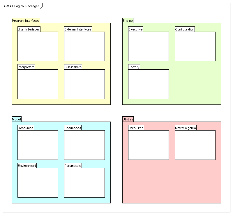
The GMAT architecture can be described as a set of components grouped into functional packages1 thatinteract to model spacecraft missions. The system is built around four packages that cooperatively interact to model spacecraft in orbit. Figure 1.1 shows an overview of this package grouping. GMAT functionality can be broken into Program Interfaces, the core system Engine, the Model used to simulate spacecraft and their environment, and Utilities providing core programmatic functionality. The constituents of these packages are described throughout this document; this chapter provides a framework for the more detailed discussions that follow. Each of these functional categories can be broken into smaller units. The next level of decompositionis also shown in Figure 1. This next level of packaging — referred to as "subpackaging" in this document — provides a ?ner grained view of the functions provided in each package. The next level of decomposition below the sub-packages provides a view into the class structure of GMAT, as will be seen in the next few paragraphs.
Figure 1: Top Level GMAT Packages: Logical Grouping
Package and Sub-package Descriptions
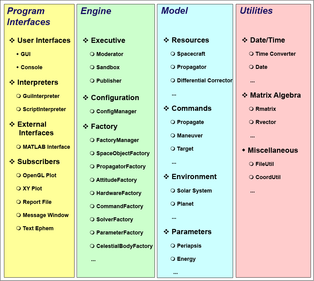
Figure 2 presents the packages and sub-packages in a slightly different format from that shown in thelast ?gure. The top level packages are represented by speci?c colors matching those in Figure 12. Thepackage names are listed at the top of each column, with the sub-packages shown indented one level from these packages. One additional level is shown in this diagram, showing representative members of the sub-packages.The deepest level items in this ?gure are classes contained in the sub-packages; for example, the Executive sub-package in the Engine package contains the Moderator, Sandbox, and Publisher classes. These elements will be used in the discussion of how the packages interact in the next few pages of this document. As is shown in these ?gures, three of these packages can be further broken into sub-packages. The following paragraphs present an overview of the packages and their subdivisions.
Program Interfaces: All two-way communications between users and external programs and GMAT arecontained in the Program Interface package. This package can be broken into four sub-packages:
- User Interfaces: Users view GMAT through a user interface — usually through the GMAT Graphical User Interface (GUI), but also potentially through a command line interface into GMAT called the GMAT console application, or Console. These interfaces are contained in the UserInterface sub-package. GMAT's GUI is coded using the wxWidgets cross-platform library[?]. The GUI provides a rich environment that provides access to all of the features of GMAT through either panels customized for each component, or through a text based script. Missions saved from the GUI are saved in the script format, and scripts loaded into the GUI populate the GUI elements so that they can be viewed on the customized interface panels. The console version of GMAT can be used to run script ?les and generate text data with little user interaction. The console application can run multiple scripts at once, or individual scripts one at a time. This version of the system is currently used for testing purposes, in situations where the overhead of the full graphical user interface is not needed.
- Interpreters: The user interface components communicate with the core GMAT system through an interface layer known as the Interpreter sub-package. This layer acts as the connection pointfor both the scripting interface and the GUI into GMAT. The Interpreter sub-package contains two speci?c interpreters: a GuiInterpreter, designed to package messages between the GUI and the GMAT engine, and the ScriptInterpreter, designed to parse script ?les into messages for the engine, and to serialize components in the engine into script form for the purposes of saving these objects to ?le. The Interpreter sub-package is designed so that it can be extended to provide other means of controlling the GMAT engine. All that is required for this extension is the development of a new interpreter, and interfaces for this new component into the Moderator, a component of the Executive sub-package in GMAT's Engine package.
- External Interfaces: GMAT provides an interface that can be used to communicate with externalprograms3. These interfaces are packaged in the ExternalInterfaces sub-package.
- Subscribers: Users view the results of a mission run in GMAT through elements of the Subscriber sub-package. Subscribers are used to generate views of spacecraft trajectories, plots of missionparameters, and reports of mission data in ?le form.
Figure 2: Packages, Sub-packages, and Some Details
Sub-packages are indicated by a cluster of diamonds Objects and Classes are marked by a circle Other constructs are marked by a single diamond
The Engine: The interfaces described above exist on top of a core simulation engine used to control themodel of flight dynamics problems in GMAT. This engine consists of the control and managementstructures for the program. The elements of the model used to simulate the spacecraft mission areintroduced in the next package description. The Engine package consists of three sub-packages:
- Executive: The Executive sub-package contains the central processing component for GMAT (called the Moderator), a connection point used to capture and distribute the results of a mission run (the Publisher), and the workspace used to run a mission (the Sandbox). The Moderator acts as the central communications hub for the GMAT engine. It receives messages from the program interfaces through the interpreters, and determines the actions that need to be taken based on these messages. The Moderator sends messages to the other components of the Engine to accomplish the requested tasks. GMAT is designed to run missions inside of a component called the Sandbox. When a user requests a mission run, the Moderator sets up the Sandbox with the elements configured for the run, and then turns control over to the Sandbox to execute the mission. The Publisher acts as the connection between data generated in the Sandbox and the views of these data presented to the User. It receives data or instructional messages from the components in the Sandbox, and passes those messages to the corresponding Subscribers.
- Configuration: When GMAT builds a model, it starts by building components that will be connected together based on a sequence of instructions. Each component is an instance of a GMAT class; as they are built, these components are stored in a local repository of objects. The repository holding model components is known as the Configuration. The Configuration sub-package consists of this repository and an interface used to access it, called the ConfigurationManager. The components stored in the configuration are all derived from a base class named GmatBase, described in Chapter 17?. In GMAT, every object that a user creates and uses to simulate a spacecraft mission is derived from this base class. The configuration is maintained as a collection of pointers to GmatBase objects. The ConfigurationManager works with this collection to maintain the configuration repository.
- Factory: The model elements stored in the configuration are created on request from the users. The sub-package responsible for processing requests for new model elements is the Factory sub-package. It consists of an interface into the sub-package — the FactoryManager — and a collection of factory classes used to create speci?c types of model elements. Each factory in GMAT creates objects based on the type requested. For example, Spacecraft or Formation objects are created through a call is the corresponding type of object into the SpaceObjectFactory. Similarly, if a user needs a Prince-Dormand 7(8) integrator, a call is madeto the PropagatorFactory for that type of integrator. The factory creates the object through acall to the class's constructor, and returns the resulting object pointer. The Factory sub-package is constructed this way to facilitate extensibility. Users can add user generated classes by creating these classes and a Factory to instantiate them. That factory can then be registered with GMAT's FactoryManager, and users will be able to access their specialized classes in GMAT without modifying the configured GMAT code base. Eventually, users will be able to load their objects through shared libraries (aka dlls in the Windows world) at run time. The FactoryManager registration process takes a factory and asks it what type of objects it can create, and sends the corresponding requests to the correct factory. Details of the factories themselves can be found in Chapter ??. Extensibility is discussed in Chapter 17?.
The Model: The Engine package, described above, provides the programmatic framework necessary forbuilding and running a simulation in GMAT. The objects that are used to model the elements of thesimulation are contained in the Model package. All of the elements of the Model package are derivedfrom a common base class, GmatBase, described in Chapter ??. When a user configures GMAT to simulate a spacecraft mission, the user is configuring objects in theModel package. In other words, the Model package contains all of the components that are available toa user when setting up a mission in GMAT. The model elements can be broken into four sub-packages:
- Environment: The environment sub-package provides all of the background environmental data used in GMAT to model the solar system, along with the components needed to perform conversions that require these elements.
- Resources: All of the model elements that do not require some form of sequential ordering inGMAT are called Resources. These are the model elements that appear in the Resource tree inthe GUI — excluding the Solar System elements — and they are the elements that are stored inthe configuration sub-package, described above.
- Commands: Commands are the elements of the model that describe how the model should evolve over time. Since commands are sequential, they are stored separately, and in sequential order, in the Command sub-package. The sequential set of commands in GMAT is called the Mission Control Sequence. The Mission Control Sequence is a list of commands. Commands that allow branching manage their branches through "child" lists. These branch commands can be nested as deep as is required to meet the needs of the model.
- Parameters: Parameters are values or data containers (e.g. variables or arrays) that exist external to other objects in the GMAT model. These objects are used to perform calculations of data useful for analysis purposes.
Utilities: The Utility package contains classes that are useful for implementing higher level GMAT functions.These core classes provide basic array computations, core solar system independent calculations, andother useful low level computations that facilitate programming in the GMAT system.
Package Component Interactions
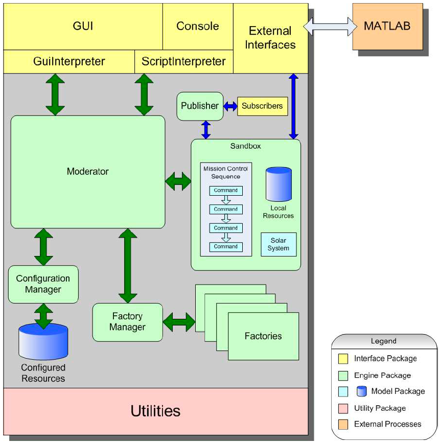
The preceding section provides a static view into the components of GMAT. In this section, a high level view of the interactions between the elements of these packages will be described. Figure 1 shows the static package view of GMAT. Each top level package is color coded so that the system components shown in the interaction diagram, Figure 3, can be identi?ed with their containing package. The legend on the ?gure identi?es the package color scheme.
Users interact with GMAT through either a Graphical User Interface (GUI) written using the cross-platform GUI library wxWidgets, or through a console-based application designed to run scripts withoutdisplaying graphical output. These interfaces communicate with the GMAT engine through interpretersingletons4.
The GUI application interacts with the engine through both the Script and GUI Interpreters,while the console application interacts through the script interpreter exclusively. These interpreters aredesigned to mediate two-way communications between the GMAT engine and users. The GUI and console applications drive the GMAT engine through these interpreters. The Interpreters in turn communicate with GMAT's Moderator singleton.
The Moderator is the centralcontrol object in the GMAT engine. It manages all program level communications and information flowwhile the program is running. It receives messages from the interpreters, processes those messages, andinstructs other components of the engine to take actions in response to the messages. The messages sent by the interpreters fall into several distinct groups:
Figure 3: Subsystem Interactions in GMAT
Green arrows show information ?ow between the core Engine components, while blue arrows show information flow that occurs when a mission is executed.
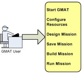
Figure 4: User Interactions
- Object Creation messages are used to request the creation of resources stored in the configuration database or the creation of commands stored in the Mission Control Sequence.
- Object Retrieval messages are used to access created objects, so they can be modi?ed by users or stored to ?le.
- Run messages prepare the Sandbox for a run of the Mission Control Sequence, and then launch execution of the Mission Control Sequence.
- Polling messages are used to control an executing Mission Control Sequence, and are used to coordinate external communications (for example, the startup process for MATLAB) and user actions taken during the run.
The message and information flow in the Engine are shown in Figure 3 with double headed arrows. The green arrows show the central message and information flow in the engine, while the blue arrows show information flow that occurs while a mission control sequence is executing. These messages are described brie?y here, and more completely through examples later in this chapter. The Moderator responds to requests for new resources or commands by requesting a new object from the FactoryManager. The FactoryManager determines which Factory class can supply the requested object, and sends a "create" request to that factory. The Factory builds the requested object, and sends the pointer to the new object to the FactoryManager, which in turn sends the pointer to the Moderator. The Moderator sends the new object's pointer to one of two locations, depending on the type of object created. If the object is a Resource, the object pointer is passed to the ConfigurationManager. The ConfigurationManager adds the resource to the database of configured objects. If the requested object is a command, it is added to the Mission Control Sequence. The Moderator then returns the pointer to the interpreter that requested the new object. Object retrieval is used to retrieve the pointer to an object that was previously created. The Moderator receives the message asking for the object. If the object is a configured resource, it calls the ConfigurationManager and asks for the resource by name. Otherwise, it traverses the Mission Control Sequence until it ?nds the requested command, and returns the pointer to that command. Run messages are used to transfer the resources and Mission Control Sequence into the Sandbox and start a run of the mission. When the Moderator is instructed to run a Mission Control Sequence, it starts by loading the configured components into the Sandbox. The Moderator requests objects from the ConfigurationManager, by type, and passes those objects to the Sandbox. The Sandbox receives the object pointers, and clones each object into a local resource database. These local clones are the objects that interact with the commands in the Mission Control Sequence to run a mission. The Moderator then passes the Mission Control Sequence to the Sandbox so that the Sandbox has the list of commands that need to be executed to run the mission. Next Moderator tells the Sandbox to initialize its components. The Sandbox initializes each of the local components, and establishes any necessary connections between components in response to this message. Finally, the Moderator instructs the Sandbox to execute the Mission Control Sequence. The Sandbox starts with the ?rst command in the sequence, and runs the commands, in order, until the last command has executed or the run is terminated by either a user generated interrupt or an error encountered during the run. Polling messages are used to process messages between the Moderator and the Sandbox during a run.Typical messages processed during polling are user requests to pause or terminate the run, or to open a connection to an external process (including the startup of that process). The descriptions provided here for these message types may be a bit confusing at ?rst. The following section provides representative cases of the message passing and object interactions in GMAT when a user performs several common interactions.
GMAT Workflow Overview
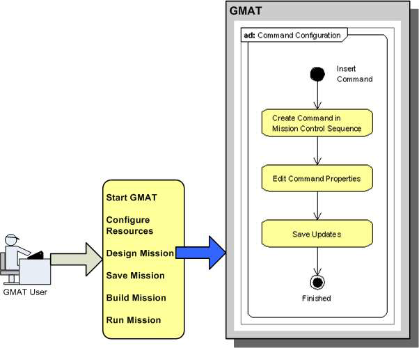
When users run GMAT, they follow a work flow like that shown in Figure 4. Users start the program,configure resources, plan their mission, save the configuration, build the mission if working from a script?le, and run the mission. The following sections describe the top level actions taken by GMAT when a user initiates each of these actions.
The GMAT Startup Process
Figure 5: The Startup Process
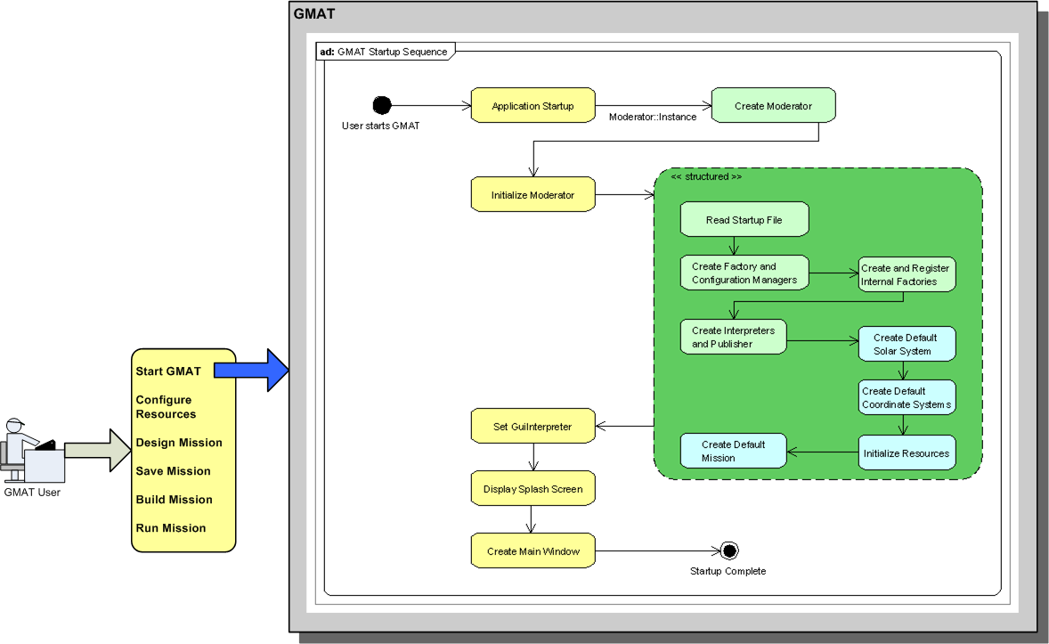
The startup process for GMAT, shown in Figure 5, launches the executable program and prepares the engine for use. Most of the work performed during startup is performed by the Moderator. When the application launches, the ?rst action taken is the creation of the Moderator singleton, made by calling the static Instance() method on the Moderator class. This freshly created Moderator is then initialized by the application through a call to the Initialize method. The procedure followed in Initialize() is shown in the large green structured flow box in the ?gure. The Moderator reads the GMAT startup ?le, setting linkages to the default ?les needed to model and display running missions. The startup ?le resides in the same folder as the GMAT application, and contains path and ?le information for planetary ephemerides, potential models, graphical images used to provide texture maps for bodies displayed in the GUI, atmospheric model ?les, and default output paths for log ?les and other GMAT generated outputs. Upon successful read of the startup ?le, the Moderator starts creating and connecting the main components of the engine. It begins by creating the components used for building model elements. The FactoryManager and ConfigurationManager are created ?rst. Next the Moderator creates each of the internally configured factories, one at a time, and passes these instances into the Factory Manager. This process is called "registering" the Factories in other parts of this document. Upon completion of Factory registration, the Moderator creates instances of the ScriptInterpreter and GuiInterpreter singletons and the Publisher singleton. This completes the configuration of the core engine elements, but does not complete the Moderator initialization process, because GMAT starts with several default model elements. The Moderator creates a default Solar System model, populated with a standard set of solar system members. Next it creates three default coordinate systems that always exist in GMAT configurations:the Earth-Centered Mean of J2000 Earth Equator system, the Earth-Centered Mean of J2000 Ecliptic system, and the Earth-Centered Earth body-?xed system. Next the Moderator sets the pointers needed to interconnect these default resources. Finally, the Moderator creates a default mission, and upon success,returns control to the GMAT application. The Application retrieves the pointer for the GuiInterpreter, and sets this pointer for later use in the GUI.It then displays the GMAT splash screen, and then ?nally creates and displays the main GMAT Window.At this point, the GMAT GUI is configured and ready for use building models and running missions.
Configuring Resources
Figure 6: Configuration Example: Spacecraft
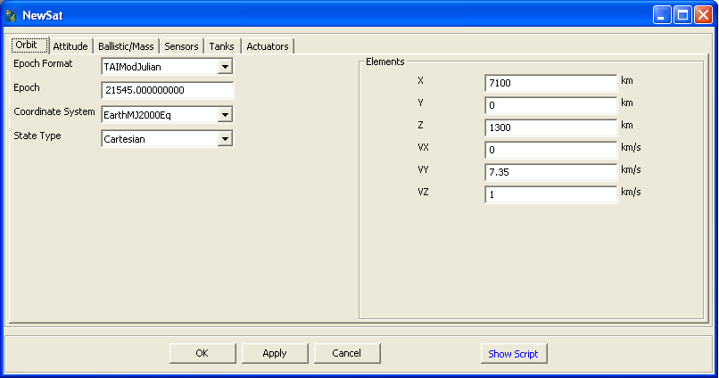
Figure 6 shows the top level set of actions taken by a user when configuring a typical resource — in this case, a Spacecraft object — from the GUI. The user starts by using a right click on the Spacecraft folder(or control-click on the Mac) in the resource tree on the left side of the main GMAT window. This action opens a context menu; the user selects "Add Spacecraft" from this menu, and a new spacecraft resource appears in the resource tree. This action is represented by the box labeled "Create the Spacecraft" in the?gure. The user may also elect to change the name of the new Spacecraft. This action is taken with a right click (control-click on the Mac) on the new resource in the resource tree, and selecting "Rename" from the resulting context menu. Once a resource has been created, the user can edit the properties of the resource. From the GUI, this action is performed with a double click on the resource. The double click opens a new panel tailored to the type of resource that is selected; for a Spacecraft, the panel shown in Figure 7 opens. The second block in Figure 6, labeled "Set Spacecraft Properties", represents the actions taken in GMAT when the user performs this selection, and when the user makes changes on the resulting panel.
Figure 7: The Spacecraft Configuration Panel
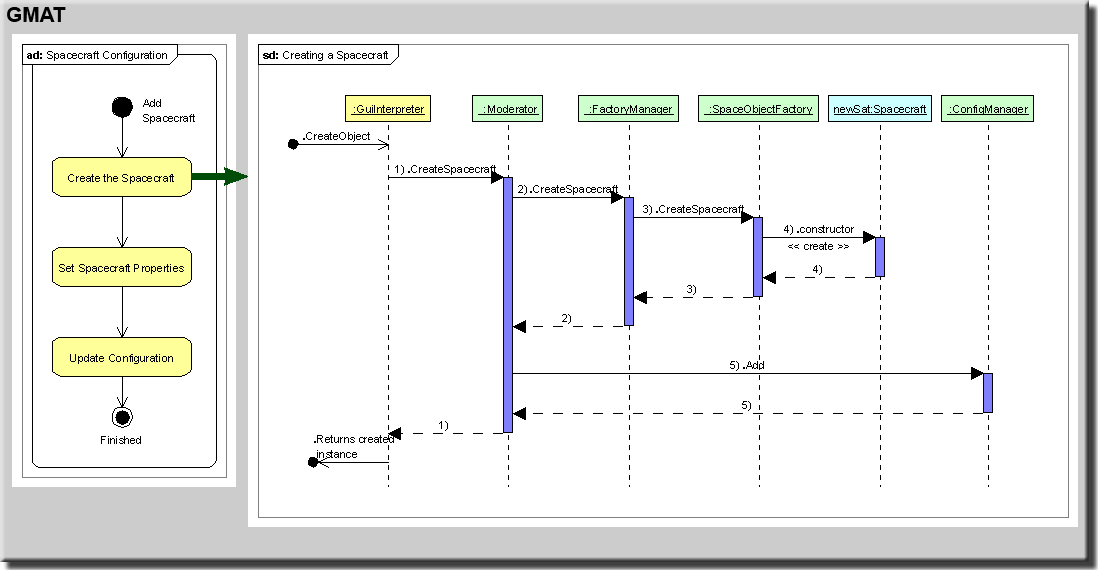
Changes made in a GUI panel like the one shown here are not automatically made on the underlying objects in GMAT. Changes made on the panel are fed back to the internal objects when the user selects either the "Ok" or "Apply" button on the bottom of the panel. This updating of the resource is represented by the "Update Configuration" block in Figure 6. Each of these blocks can be further decomposed into the internal actions performed in GMAT when the user makes the selections described here. The following paragraphs describe in some detail how GMAT reacts to each of these user actions. 1.2.2.1 Creating the Spacecraft Figure 8 shows an example of the process followed in GMAT when a new resource is created from the GUI. The user selected "Add Spacecraft" from the option menu on the Spacecraft node of the resource tree (accessed with a right click — control-click on the Mac — on the node). This selection triggered the chain of events shown in the sequence diagram in the ?gure5. The sequence starts with a CreateCbject() call from the GUI to the interface into the GMAT engine. The interface between the GUI and the GMAT engine is a singleton instance6 of the GuiInterpreter class, and is shown in green in the ?gure.
Figure 8: Configuration Example: Creating the Spacecraft
The GuiInterpreter singleton receives the call to create an object of type Spacecraft. It makes a call,in turn, into the singleton responsible for running the GMAT engine. This singleton is an instance of the Moderator class7. The call into the Moderator is made in step 1 of the diagram; the call is made through the GreateSpacecraft() method of the Moderator. User configured objects in GMAT are always created through calls into a subsystem referred to collectively as the Factory subsystem. Factories are responsible for creating these objects. The factory subsystem is managed through a singleton class, the FactoryManager. The Moderator accesses the factories through this singleton. In step 2 of the ?gure, the Moderator makes a call to the CreateSpacecraft() method on the FactoryManager. The FactoryManager ?nds the Factory responsible for creating objects of the type requested — in this case, a Spacecraft object — and calls that factory in turn. Spacecraft are created in GMAT's SpaceObjectFactory, so the FactoryManager calls the GreateSpacecraft() method on the SpaceObjectFactory, as is shown in step 3. The SpaceObjectFactory creates an instance of the Spacecraft class by calling the class's constructor, as shown in step 4. The constructed object is given a name, and then returned through the FactoryManager to the Moderator. The Moderator receives the new object, and adds it to the database of configured objects in GMAT. All configured GMAT objects are managed by a singleton instance of the ConfigurationManager class.The ConfigurationManager is used to store and retrieve objects during configuration of the model. The Moderator adds created components to the configuration by calling Add() methods on the Configuration-Manager. For this example, the new Spacecraft is added to the configuration through the call shown in step 5. Once the steps described above have been completed successfully, the Moderator returns control to the GuiInterpreter, which in turn informs the GUI that a new object, of type Spacecraft, has been configured. The GUI adds this object to the resource tree, and returns to an idle state, awaiting new instructions from the user.
Setting Spacecraft Properties
The Spacecraft that was created above has default settings for all of its properties. Users will typically reset these properties to match the needs of their mission. The process followed for making these changes from the GUI is shown in Figure 9.
Figure 9: Configuration Example: Setting Spacecraft Properties
As was discussed in the introduction to this section, Spacecraft properties are set on the GUI panel shown in Figure 7. Users can open this panel at any point in the model setup process. Because of the free flow in the configuration process, the Spacecraft pointer may not be accessible when the user elects to open the configuration panel with a double click on the Spacecraft's name on GMAT's resource tree. Therefore, the ?rst action taken when the panel is opened is a call from the panel to the GuiInterpreter to retrieve the configured Spacecraft with the name as speci?ed on the Resource tree. The GuiInterpreter passes this request to the Moderator. The Moderator, in turn, asks the ConfigurationManager for the object with the speci?ed name. The ConfigurationManager returns that object to the Moderator, which passes it to the GuiInterpreter. The GuiInterpreter returns the object (by pointer) to the Spacecraft Panel. The Spacecraft Panel creates a temporary clone of the configured spacecraft so that it has an object that can be used for intermediate property manipulations8. This clone is set on the Spacecraft Panel's subpanels, accessed through a tabbed interface shown in the snapshot of the panel. Each subpanel accesses the properties corresponding to the ?elds on the subpanel, and sets its data accordingly. The Spacecraft Panel is then displayed to the user. The user then makes any changes wanted for the model that is being configured.
Saving the Spacecraft
Figure 10: Configuration Example: Saving the Spacecraft
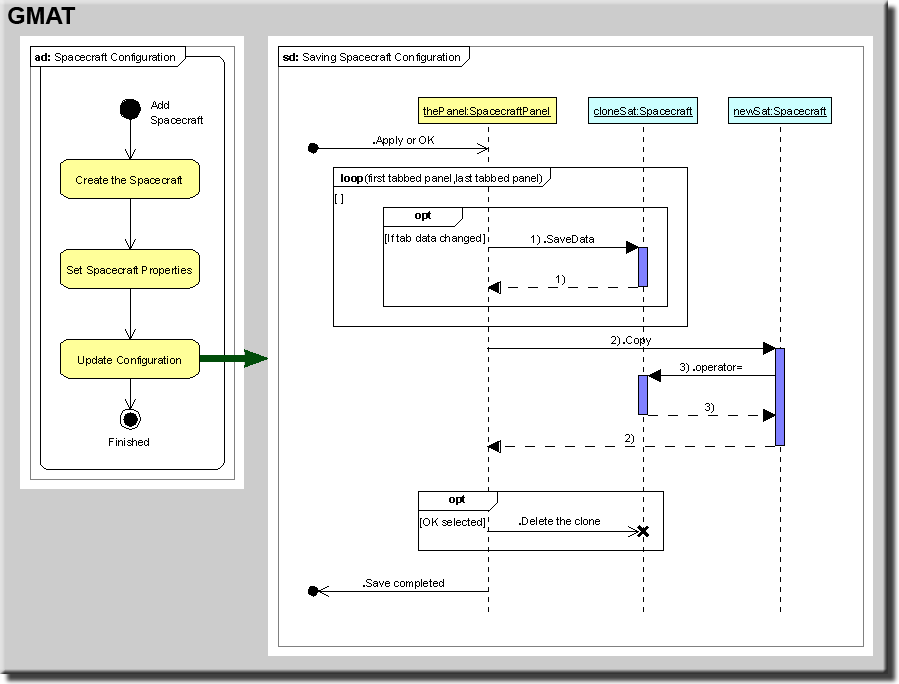
The ?nal step in the spacecraft configuration process is saving the updated data into the configuration.That process is shown in Figure 10. The Spacecraft Panel has several tabbed subpanels. The SpacecraftPanel begins the save process by calling each of these subpanels in turn, setting the corresponding Spacecraft data one subpanel at a time on the locally cloned Spacecraft. Once all of the subpanels have synchronized their data with the clone, the copy constructor of the configured Spacecraft is called with the cloned Spacecraft as the input argument.This action updates the configured Spacecraft, completing the save action. There are two buttons on the Spacecraft Panel that can be used to perform the save action. The button labeled "Apply" saves the updated data to the configured object and leaves the Spacecraft Panel open for further user manipulation. The "OK" button saves the data and closes the panel. The latter action destroys the instance of the panel. Since the panel is going out of scope, the cloned Spacecraft must also be deleted, as is shown in the ?gure.
Configuring Commands
The previous paragraphs describe the interactions between core GMAT components and the internal message passing that occurs when a component of a GMAT Model is configured for use. The following paragraphs describe the analogous configuration for the commands in the Mission Control Sequence.
Figure 11: The Mission Tree in GMAT's GUI
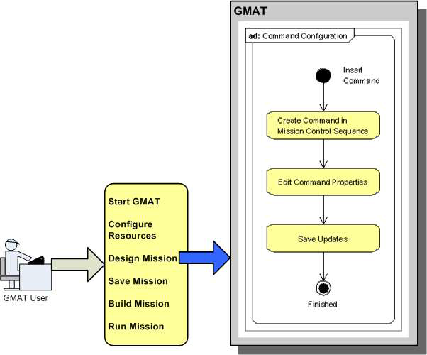
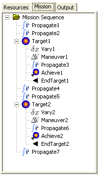
The Mission Control Sequence is shown in the GMAT GUI on the tab labeled "Mission," shown for a modi?ed Hohmann transfer problem9 in Figure 11. The sequence is shown as a hierarchical tree of commands. Each level of the hierarchy is a separate list of commands. The top level list is the main control sequence. Commands that branch from this list are shown indented one level from this sequence. Commands branching off of these commands are indented an additional level10). This process continues until all of the commands in the sequence are incorporated into the tree structure. The Mission Control Sequence shown in the ?gure consists of seventeen commands, grouped as seven commands in the main (i.e. top level) sequence, ?ve additional commands branched off of this sequence to perform one set of maneuver targeting, and an additional ?ve commands to perform targeting for a second maneuver. The main sequence of commands shown here is the sequence Propagate — Propagate — Target — Propagate — Propagate — Target — Propagate. The Target commands are used to tune the maneuvers at each end of the transfer orbit by applying the command sequence Vary — Maneuver — Propagate — Achieve — EndTarget. The inner workings of these commands are beyond the scope of this document; the important thing to observe at this point is the sequencing of the commands, and the presentation of this sequencing to the user by way of GMAT's GUI. The tree shown in the GUI is populated by traversing the linked list of commands comprising the MissionControl Sequence. Each node of the Mission Tree is an instance of the class MissionTreeItemData. This class includes a pointer to the corresponding GmatCommand object in the Mission Control Sequence. When GMAT needs to build or refresh the Mission Tree, it accesses the ?rst node in the Mission Control Sequence and creates a corresponding MissionTreeItemData instance. That instance is passed the pointer to the GmatCommand, and uses that command pointer to configure its properties in the tree. GMAT then asks for the next node in the sequence, and repeats this operation until the tree is fully populated. Some GmatCommands are derived from a subclass named BranchCommand. These commands managechild linked lists, like the ones shown for the target commands in the ?gure. When the GUI encounters a BranchCommand derivative, it indents the nodes displayed on the Mission Tree to indicate this nested level for the child sequence of the branch command. All of the commands that allow this type of nesting are terminated with a corresponding "End" command — for this example, the Target command terminates the targeting child sequence when it encounters an EndTarget command. Users interact with the Mission Control Sequence either through GMAT's scripting interface, or through manipulations made in the GUI. Manipulations made while scripting are pretty straightforward; they consist of editing a script ?le of commands and then instructing GMAT to parse this script. This process will be described later. Figure 12 shows the steps a user takes when adding a command to the Mission Control Sequence from the GUI.
Figure 12: Configuration Example: A Mission Control Sequence Command
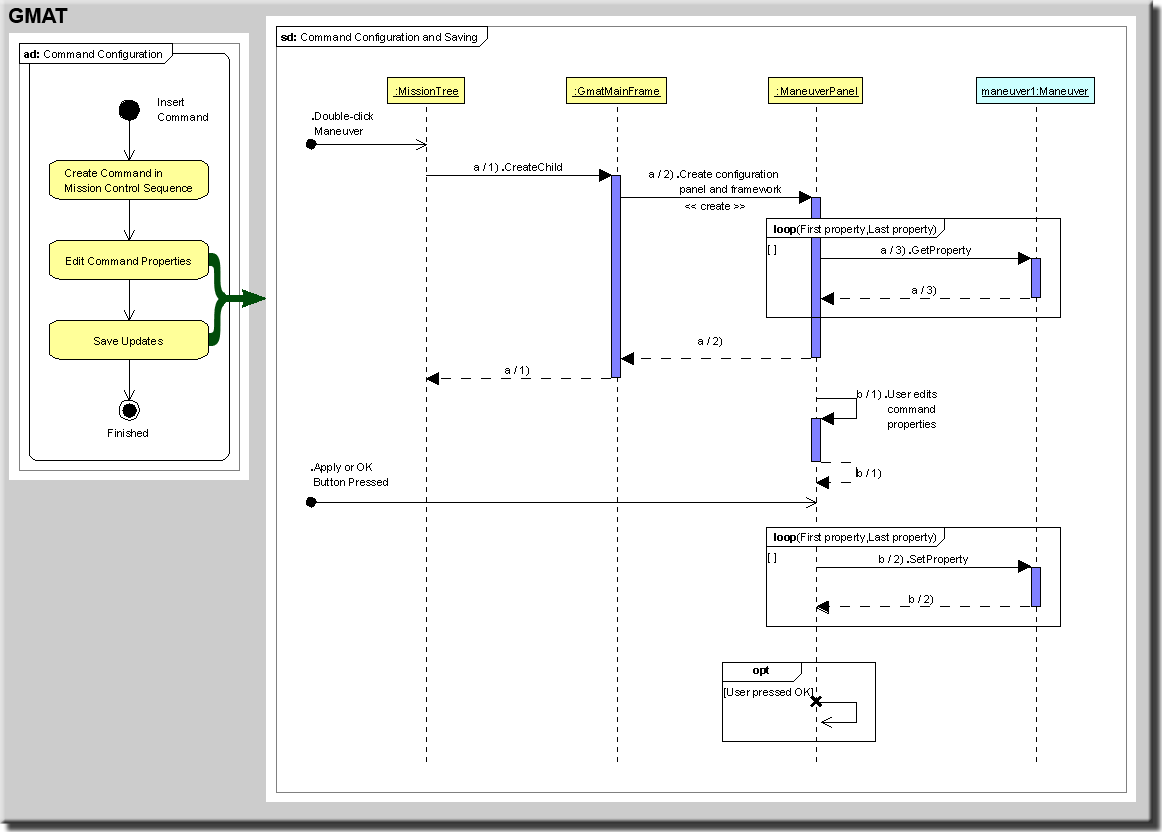
The Mission Control Sequence is a doubly linked list of objects that describes the sequence of actions that GMAT will run when executing a mission. Each node in the linked list is an object derived from the command base class, GmatCommand, as is described in Chapter ??. Since GmatCommand objects are doubly linked in the list, each command has a pointer to its predecessor and to the next command in the list. When a user decides to add a command to the Mission Control Sequence, a node in the Mission tree is selected and right clicked (or control-clicked on the Macintosh). This action opens a context menu with "Insert Before" and "Insert After" submenus as options. The "Before" and "After" selections here refer to the location of the new command. The user selects the desired command type from the submenu, and the requested command is added to the Mission Control Sequence in the speci?ed location. This set of actions corresponds to the ?rst block in the activity diagram, labeled "Create Command in Mission Control Sequence." Most of the commands in GMAT require additional settings to operate as the user intends — for example,Propagate commands require the identity of the propagator and spacecraft that should be used during propagation. The second block in the ?gure, "Edit Command Properties," is launched when the user double clicks on a command. This action opens a command configuration panel designed to help the user configure the selected command. The user edits the command's properties, and then saves the updates back to the command object by pressing either the "Apply" or "OK" button on the panel. This action is performed in the "Save Updates" block in the ?gure, and is the ?nal step a user takes when configuring a command. Each of these high level actions can be broken into a sequence of steps performed between the core elements of GMAT, as is described in the following paragraphs, which describe the interactions followed to add a Maneuver command to the Mission Control Sequence.
Creating a Maneuver Command
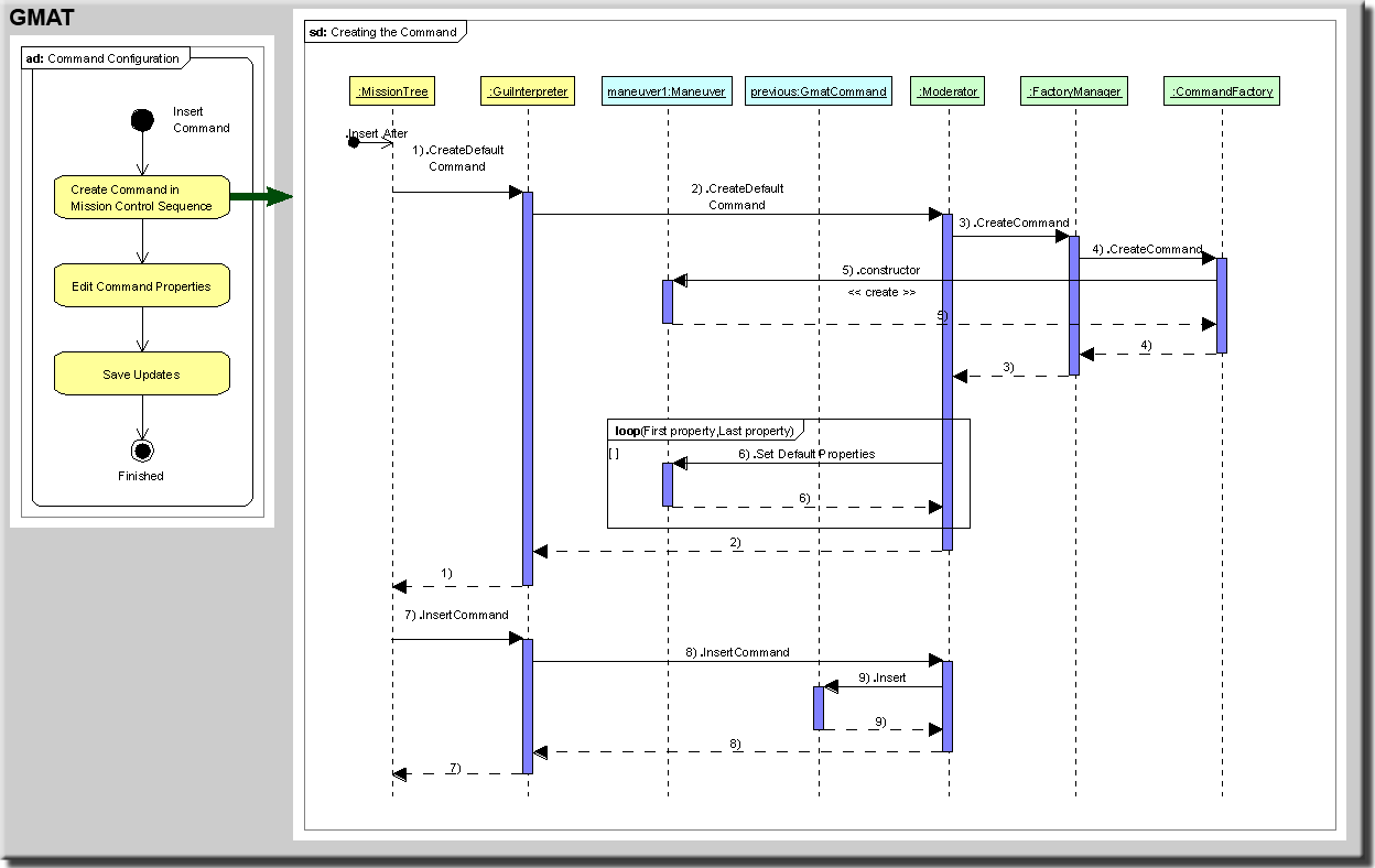
Figure 13 shows the process followed when a Maneuver command is created and inserted following an existing command from the GMAT GUI. The process starts when the user selects a command on the mission tree, right clicks it, and chooses the "Insert After" option from the resulting context menu. The resulting submenu contains a list of available commands; the following actions occur when the user selects "Maneuver" from this list.
Figure 13: Command Creation Example – Creating a Maneuver Command
Maneuver command creation starts when the MissionTree11 object sends a request to the GuiInterpreterfor a new Maneuver command instance. The GuiInterpreter sends the request to the Moderator, which sends the request to the FactoryManager. The FactoryManager ?nds the factory that creates Maneuver commands, and asks that factory for an instance of the Maneuver command. The resulting instance is returned from the factory, through the FactoryManager, to the Moderator. The Moderator sets some default data on the command, and then returns the command pointer to the GuiInterpreter. The GuiInterpreter passes the command pointer to the MissionTree. Each node in the MissionTree includes a data member pointing to the corresponding command in the Mission Control Sequence. This structure simpli?es the interactions between the GUI and the engine when a user makes changes to the Mission Control Sequence. Since the MissionTree already has a pointer to the command preceding the new Maneuver command, it has all of the information needed to request that the new command be added to the Mission Control Sequence. The new Maneuver command is added to the Mission Control Sequence from the MissionTree. The MissionTree passes two pointers through the GuiInterpreter to the Moderator: the ?rst pointer identi?es the command selected as the command preceding the new one, and second pointer is the address of the new Maneuver command. The Moderator passes these two pointers to the head of the Mission Control Sequence using the "Insert" method. This method searches the linked list recursively until it ?nds the node identi?ed as the previous command node, and adds the new command immediately after that node in the list, resetting the linked list pointers as needed. This completes the process of adding a command to the Mission Control Sequence.
Configuring and Saving the Maneuver Command
When a new command is added to the Mission Control Sequence, it is incorporated into the sequence with default settings selected by the Moderator. Most of the time, the user will want to edit these settings to match the requirements of the mission being modeled. Command configuration is performed using custom panels designed to display the properties users can set for each command. Figure 14 shows the panel that opens when a user double clicks a maneuver command — like the one created in the example described above — in the mission tree.
Figure 14: The Maneuver Command Configuration Panel
The sequence diagram in Figure 15 shows the top level messages that are passed when the Maneuver command is configured using this panel. This view into the command configuration includes a bit more detail about the GUI messages than was shown in the Spacecraft configuration presented previously. The configuration process starts when the user double clicks on the command in the mission tree. The double click action sends a message to the MissionTree requesting the configuration panel for the selected node in the tree. The Mission Tree ?nds the item data, and sends that data to the main GMAT window, called the GmatMainFrame, asking for a new child window configured to edit the properties of the command contained in the item data. The GmatMainFrame creates the child window and displays it for the user.
Figure 15: Command Configuration Example: Configuring the Maneuver Command
More concretely, if the user double clicks on the Maneuver command created in the preceding section,the tree item data for that maneuver command is passed from the Mission Tree to the Gmat MainFrame.The configuration window that should result from this action for display in the GUI needs to contain the panel designed to match the underlying object that is being configured — in this case, a Maneuver command.The Gmat MainFrame uses the tree item data passed to it to determine the type of panel needed by the child window during its creation. For this example, the Gmat MainFrame determines that the panel that is needed should be a Maneuver Panel because the tree item data includes a pointer to a Maneuver command. Accordingly, the Gmat MainFrame creates an instance of the Maneuver Panel class, and passes that panel to the child window. The child window receives the panel and places it into the corresponding container in the window. Finally, the child window uses the command pointer in the tree item data to access the command and determine the current values of its internal properties. These data are collected from the command and passed to the corresponding GUI components so that the user can see the current settings. Once these data ?elds have been populated, the child window is displayed on the GUI, giving the GUI a new window like that shown in Figure ?gure:Maneuver Con?gPanel. This completes the top portion of the sequence shown in Figure 15. Once the panel is shown on the GUI, the user makes changes to the settings for the command on the new panel. When the settings match the needs of the mission, the user clicks on either the "OK" or "Apply" button. This action makes the Maneuver Panel update the Maneuver command with the new settings. If the user pressed the OK button, the child window also passes a message to GMAT indicating that the user is ?nished with the window. When that message is processed, the child window is closed in the GUI.
Model and Mission Persistence: Script Files
GMAT saves configuration data in ?les referred to as script ?les. The details of the script ?le parsing can be found in Chapter ??. The following paragraphs provide an overview of these processes.
The GMAT script ?les can be thought of as a serialized text view of the configured objects and Mission Control Sequence constructed by the user to model spacecraft. GMAT provides a subsystem, controlled by the ScriptInterpreter that manages reading and writing of these ?les. All of these script ?les are ASCII based ?les, so they can be edited directly by users.
1 2 3 4 5 6 7 8 9 10 11 12 13 14 15 16 17 18 19 20 21 22 23 24 25 26 27 28 | % — — — — — - - - - - - - — — — — — — — — — — — — — - - - - - - - — — — — — — — — — -- Create Spacecraft sat1 sat1.ECC = 0.25 sat1.INC = 78.5 sat1.RAAN = 45
Create ForceModel fm fm.PrimaryBodies = {Earth} fm.PointMasses = {Luna, Sun}
posve1.IndVar = sat1.X posve1.Add = sat1.VY posve1.Add = sat1.VZ
% - - - - - - - - - - - - - - - - - - - - - - - - - - - - - - - - - - - - - - - - - - - % - - - - - - - - - - - - - - - - - - - - - - - - - - - - - - - - - - - - - - - - - - - Propagate prop(sat1) % Endwhile |
Listing 1: A Basic GMAT Script File
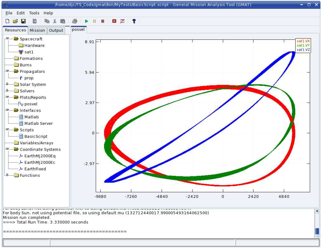
Listing 1.1 shows a simple script that propagates a spacecraft for approximately 7 days, plotting the Cartesian components of the velocity against the spacecraft’s X coordinate value. Details of all of these settings can be found in the User’s Guide[?]. This script just serves as an example for the discussion that follows.
All objects that are created as configured resources from the GUI are stored in the script ?les using the keyword “Create”. In the script shown here, there are four resources: a Spacecraft named “satl”, a ForceModel named “fm”, a Propagator (actually an instance of the PropSetup class) named “prop”, and an XYPlot Subscriber named “posvel”. Each of these resources is used when running the mission.
In GMAT, each resource can have one or more data members that users can set. These resource properties are initialized to default settings. Users can override the values of these properties. In the GUI, this action is performed by editing data presented on the panels for the resources. Properties are changed in the script ?le by assigning new values to the properties by name; for example, in the sample script, the Spacecraft’s semimajor axis is changed to 10000.0 km on the ?fth line of script:
sat1.SMA = 10000.0 |
The script shown here is a script as it might be entered by a user. Only the lines that override default property values are shown, and the lines are written as simply as possible. The full set of object properties can be examined by writing this object to a script ?le. When a Spacecraft — or any other resource — is saved, all of the resource properties are written. In addition, the keyword “GMAT” is written to the ?le, and the full precision data for the numerical properties are written as well. The Spacecraft configured in the script ?le above is written to ?le as shown in Listing 1.2.
1 2 3 4 5 6 7 8 9 10 11 12 13 14 15 16 | Create Spacecraft sat1; GMAT sat1.DateFormat = TAIModJulian; GMAT sat1.Epoch = 21545.000000000; GMAT sat1.CoordinateSystem = EarthMJ2000Eq; GMAT sat1.ECC 0.2499999999999999; GMAT sat1.INC = 78.5; GMAT sat1.RAAN = 45; GMAT sat1.AOP = 7.349999999999972; GMAT sat1.TA = 0.9999999999999002; GMAT sat1.DryMass = 850; GMAT sat1.Cd = 2.2; GMAT sat1.Cr = 1.8; GMAT sat1.DragArea = 15; GMAT sat1.SRPArea = 1; |
Listing 2: Script Listing for a Spacecraft
GMAT generates the scripting for resources and commands using a method, GetGeneratingString(), which is provided in the GmatBase class. This class provides the infrastructure needed to read and write object properties through a consistent set of interfaces. The GetGeneratingString() method uses these interfaces when writing most user objects and commands to script. Derived classes can override the method as needed to write out class speci?c information. When GMAT saves a model to a script ?le, it tells the ScriptInterpreter to write a script ?le with a given name. The ScriptInterpreter systematically calls GetGeneratingString() on each object in the configuration and sends the resulting serialized form of each object to the script ?le. Once all of the objects in the configuration have been saved, GMAT takes the ?rst command in the Mission Control Sequence and calls its GetGeneratingString() method, writing the resulting text to the script ?le. It traverses the command list, writing each command in sequential order.
Script reading inverts this process. When a user tells GMAT to read a script, the name of the script ?le is passed to the ScriptInterpreter. The ScriptInterpreter then reads the ?le, one logical block1 at a time,
and constructs and configures the scripted objects following a procedure similar to that described above for actions taken from the GUI.
Details of script processing can be found in Chapter ??.
Running a Mission
Once a user has configured a model in GMAT, the model is ready to be run. The configuration has been populated with all of the resources needed for the run, and the resources have been configured to match the needs of the analyst. The Mission Control Sequence has been entered and configured to meet the needs of the mission. All that remains is the actual running of the model encoded in these elements.
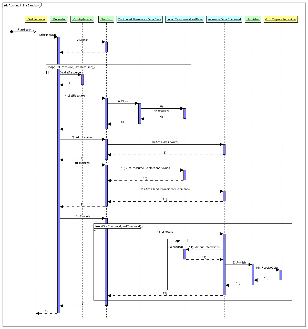
Figure 1.16 shows the sequence followed when a mission is executed in GMAT. The ?gure shows the sequence as initiated in the GUI. The user chooses to run the mission by pressing the “Run” button on GMAT’s toolbar. This action sends a RunMission message to the GuiInterpreter, which then calls the Moderator’s RunMission() method (Step 1 in the ?gure).
The Moderator begins by clearing any stale data out of the Sandbox by calling the Sandbox’s Clear() method (Step 2). This action removes any local copies of objects in the Sandbox that may still exist from a previous run. Once the Sandbox has been cleared, the Moderator begins passing resources into the Sandbox.
The Moderator passes the current Solar System into the Sandbox, and then begins making calls to ConfigurationManager to get the current set of resources used in the model (Step 3). The Moderator passes these resources into the Sandbox (Step 4) by type, starting with coordinate systems, and proceeding until all of the resources have been passed into the Sandbox. The Sandbox receives each resource as it is passed in and makes a copy of that resource by calling its Clone() method (Steps 5 and 6). The Sandbox stores these local clones by name in its local object map. The local object map contains the objects that are manipulated during a run; the configured objects are not used when running the mission.
After the configured objects have been passed into the Sandbox, the Moderator sends the head node of the Mission Control Sequence to the Sandbox2 (Step 7). This sets the Sandbox’s internal sequence pointer to the ?rst command in the Mission Control Sequence (Step 8), completing steps needed to begin work in the Sandbox.
The Moderator has completed the bulk of its work for the run at this point. The next action taken is a call from the Moderator to the Sandbox, instructing it to initialize itself (Step 9). When the Sandbox receives this instruction, it begins initializing the local objects. Each object is queried for a list of referenced objects that need to be set, and the Sandbox ?nds these objects in the local object store and sets each one on the requesting object (Step 10, performed iteratively through all of the objects). After the object initialization, the Sandbox walks through the Mission Control Sequence node by node, passing each command a pointer to the local object map and then calling the Command’s Initialize method, giving each command the opportunity to set up data structures needed to execute the Mission Control Sequence (Step 11, performed iteratively through the Mission Control Sequence). If initialization fails at any point during this process, the Sandbox halts the initialization process and reports the error to the Moderator.
Once initialization is complete, the Sandbox reports successful initialization to the Moderator. At this point the Moderator sends an Execute() message to the Sandbox (Step 12). The Sandbox responds by calling the Execute() method on the ?rst command in the Mission Control Sequence (Step 13). The command executes this method, manipulating objects in the local object map (Step 14) and sending data to GMAT’s Publisher (Step 15) based on the design of each command. When data is passed to the Publisher, it passes the data on to each Subscriber (Step 16), producing output that the user can view to monitor the mission as it executes, or to process after the mission has ?nished running.
When the ?rst command completes execution, the Sandbox asks for the next node to execute in the Mission Control Sequence, and repeats this process on the second node. The process continues, calling node after node in the Mission Control Sequence until the ?nal command has been executed.
Figure 16: The Sequence followed to Run a Mission
Figure 17: Results of the Script Example, Run on Linux
Once the ?nal command has executed, the Sandbox sends a message to the Mission Control Sequence stating that the run has completed execution, and control is returned to the Moderator from the Sandbox.
The Moderator returns control to the GuiInterpreter, which returns control, through the GUI, to the user, completing the mission run. Figure 1.17 shows the results of this sequence when executed for the script shown in Listing 1.1.
Summary
This completes the presentation of the overview of GMAT’s architecture. In this chapter we have discussed the basic architecture for GMAT, presented an overview of the arrangement of the components of the system that we will build upon in upcoming chapters, and presented a programmatic description of the work?ow of three common tasks performed in GMAT: Starting the system, Creating resources and comments for a spacecraft mission, and running that mission.
The next few chapters will present, in some detail, descriptions of each of the components of the Engine package, followed by sections describing the infrastructure used for the Resources and Commands, and then the design features of these elements.
NOTES:
Note that these divisions are functional, and not enforced by any physical packaging constraints like a namespace or shared library boundaries.
This color scheme will be used for the remainder of this chapter as well.
At this writing, the only external interface incorporated into the core GMAT code base is an interface to the MathWorks' product MATLAB[?].
The GMAT engine is run through a set of singleton class instances. The singleton design pattern used for these instances is introduced in Appendix 17?. The important thing to know about singletons for this discussion is that there is only one instance of any singleton class; hence a running GMAT executable has one and only one Scriptlnterpreter, and Moderator, and at most one GUIInterpreter. Other singletons will be introduced during this discussion as well, when the factories and configuration are discussed.
For an introduction to the UML diagram notation used throughout this document, see Appendix ??
Singletons, and other design patterns used in GMAT, are introduced on Appendix ??
For the purposes of this discussion, the singleton instances will be referred to by their class name for the remainder of this discussion.
The Spacecraft is unique in this respect; other objects configured in the GMAT GUI are manipulated directly, rather than through a clone. The Spacecraft is in many respects a composite object; this added complexity makes the intermediate clone a useful construct.
The modi?cation made here is along the transfer trajectory from the initial orbit to the ?nal orbit. The spacecraft in this example is propagated through one and a half orbits on the transfer trajectory, rather than the typical half orbit needed for the problem.
In some cases sequences of similar commands are also indented to simplify the display of the Mission Control Sequence.
Here, and throughout this document, speci?c instances of singleton classes are referred to by the class name — "MissionTree" in this case. When the class or user experience of the instance is discussed, it will be referred to less formally — "mission tree", for example. So as an example of this style, we might discuss the user selecting an object on the mission tree in the GUI, which causes the MissionTree to perform some action.
- A “logical block” of script is one or more lines of text suf?ciently detailed to describe a single action taken in GMAT. Examples include creation of a resource, setting of a single parameter on a resource, or adding a command to the Mission Control Sequence.
- Commands are not cloned into the Sandbox at this writing. A future build of GMAT may require cloning of commands as well as resources, so that the system can support multiple Sandboxes simultaneously. The system is designed to allow this extensibility when needed.
